What is Minimum Control speed VMC, or VMCA really?
VMC, or more specifically VMCA, is the AFM-published minimum speed for maintaining straight flight only when either engine fails or is inoperative and the corresponding opposite engine is set to
provide maximum thrust, provided a small favorable bank angle is being maintained of 3 to
5 degrees (exact number to be provided by the manufacturer) away from
the inoperative engine. VMC(A) applies during the whole flight, not only during takeoff.
WARNING: The actual VMC(A) that the pilot will experience when banking away from the small favorable bank angle (when keeping the wings level or during turns to either side) will be much higher than the AFM-published VMC(A), because the actual VMC(A) varies with thrust setting, bank angle and weight. Then, the actual VMC(A) will easily increase above V2 or VYSE, causing an unexpected and often fatal loss of control. In addition, the sideslip, hence drag, will increase considerable, reducing the Rate of Climb.
Minimum Control Speed - VMCA
When an engine fails or is inoperative in-flight, rudder is required to counteract the asymmetrical thrust yawing moment; roll effects are to be counteracted by the ailerons. The counteracting forces generated by these aerodynamic control surfaces are proportional to the square of the airspeed (V2), to the area of the surfaces (S) and to the air density. So, for a given size of the vertical tail with rudder, there is a speed below which the generated rudder side force ("horizontal lift") is not large enough anymore to counteract the asymmetrical thrust, or below which the ailerons are not effective anymore: the heading and/or bank angle cannot be maintained ("controlled") below this speed. This speed is called Minimum Control speed (VMC) or more appropriate: Minimum Control speed in the Air (VMCA).
VMCA is already determined (i.e.
assumed) by the design engineer for sizing the vertical tail (fin), because a
vertical tail may not be made that small that VMCA increases above 1.2
VS (FAR/CS 23.149).
On the other side, a large tail results in a lower VMCA
but in higher weight and production cost.
FAR/CS 23.149 allows the design engineer to use a small bank angle of maximum 5º
(away from the failed engine) which generates a side force that reduces the required rudder, or allows a smaller vertical tail. The small bank angle reduces both the sideslip (drag) and VMCA
while an engine is inoperative. Both the Rate of Climb (ROC) and the safety margin to the IAS increase.
However, the saved hardware weight of a smaller tail needs to be replaced by
a quite 'heavy' software condition (on paper in the AFM) for pilots when an
engine is inoperative, which is to maintain straight flight only when the airspeed is as low as VMCA, and maintain a small bank angle away from the inoperative engine for minimum drag, hence maximum rate of climb.
Read more here, and/or view the video:

|
A 42 min. video lecture, in which the real value of the minimum control speed airborne (VMCA) is explained as taught at all formal Test Pilot Schools and most aeronautical universities, including the review of two accidents using views from the cockpit, is available on YouTube. Click here A pdf file with slides and script used in this video can be downloaded here. |
Courses on asymmetric powered flight that test pilots and flight test engineers receive at formal Test Pilot Schools can be downloaded from the USArchives via the Links page), click here.
Summary of VMCA theory
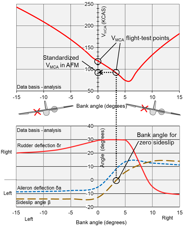
This figure shows the airspeed required for maintaining control of this sample airplane for bank angles between 15° left and 15° right when engine #1 is inoperative and #2 is at max. thrust, for rudder and aileron deflections to stay within their mechanical limits (enabling control). |
VMCA is a constant number, but only in the AFM. In flight, the actual VMCA varies with bank angle, engine thrust, rudder deflection, and other variables. This graph shows (actual) VMCA, required rudder and aileron deflections, and the resulting sideslip angle versus bank angle of
a sample airplane after failure of the left engine (#1) while the asymmetrical thrust is maximal. |
Lesson learned: The vertical tail with rudder and/or the ailerons are not designed large enough for maintaining control during turns into or away from the inoperative engine when the airspeed is, or is close to VMCA while maximum asymmetrical thrust is set, but only for maintaining straight flight. Therefore, before turning to either side, increase the airspeed by at least 30 kt.
At any sign of inadequate remaining control power (near full rudder or max. aileron), i.e. impending loss of control, decrease thrust (a bit) and recover to straight flight. After establishing the favorable bank angle, asymmetrical thrust can be increased again.
How is VMCA measured in-flight
The airplane is brought in the VMCA test configuration, i.e. lowest weight possible and aft center of gravity, which result in the highest, worst case VMCA at which straight flight can be maintained. In-flight, at a safe altitude of 5000 ft AGL, an airspeed is attained well above the anticipated VMCA (VSSE). Then the critical engine is shut down, or set at torque for zero thrust, and the opposite engine at maximum thrust. The airspeed is slowly decreased until the increasing rudder and/or aileron cannot maintain the heading and/or wings level anymore. The airspeed at which this occurs is VMCA with the wings level; also mind the large unavoidable sideslip, i.e. drag. Then, the bank angle is slowly increased into the operating engine, to a maximum of 5° or until the sideslip is zero, and the airspeed is further decreased until again the heading cannot be maintained with rudder and/or aileron. The airspeed at which this occurs is the VMCA of the airplane that will be published in the AFM, after extrapolation to sea level.
Regulations do not require the much higher actual VMCA during turns to be determined.
Please refer to the formal FAA or EASA Flight Test Guides for the safe conduct of this test, via the Links page.
VMCA Definition
| For Manufacturers: | For Pilots: |
|
FAR and EASA/CS 23.149 and equivalent present the definition of VMCA for the design and certification of multi-engine airplanes that is also inappropriately copied into most AFM's: VMC is the calibrated airspeed at which, when the critical engine is suddenly made inoperative, it is possible to maintain control of the airplane with that engine still inoperative, and thereafter maintain straight flight at the same speed with an angle of bank of not more than 5 degrees. |
Once the airplane is designed and built, the selected tail size imposes a limitation on, i.e. a constraint to, pilots. The VMCA definition for use by pilots is therefore different than the VMCA definition out of FAR/CS 23.149 that is for manufacturers, for designing and certification of multi-engine airplanes: VMCA is the minimum speed for maintaining straight flight only when an engine fails or is inoperative and the corresponding opposite engine is set to provide maximum thrust, provided a bank angle is being maintained of 3 – 5 degrees (exact number to be provided by the manufacturer) away from the inoperative engine. In addition, the manufacturer should specify the configuration for which VMCA and other published VMC's are valid. |
For further details, refer to the papers for pilots presented on the Downloads page.
Display of VMCA
|
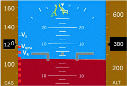
On the airspeed indicator of Part 23 twin-engine airplanes, the standardized AFM-published VMCA is indicated by a red radial line, in this example at 80 kt. However, neither a placard on the instrument panel nor a note or warning in the AFM tells the pilot that the redlined VMCA is valid only if a bank angle of 3 to 5 degrees (to be specified by the manufacturer) is maintained away from the inoperative engine. A larger bank angle, or a bank angle into the inoperative engine results in a much higher actual VMCA, a 14 or more degree sideslip, hence large drag, and to the loss of climb performance and possibly loss of control after which an accident cannot be avoided (when asymmetrical thrust is not reduced). |
|
The airspeed for maximum single-engine rate of climb VYSE is indicated by a blue radial line, here at 105 kt. In the legend of some Performance Data Tables of Graphs, a note tells the pilot that the presented performance data, including the performance at VYSE, are valid only if a small bank angle is being maintained of 2 - 3 degrees away from the inoperative engine. For other bank angles, the maximum climb performance or the performance to maintain altitude (i.e. to prevent drifting down) is not guaranteed. Dr. Jan Roskam (KU): "The VMCA value ultimately used ties take-off performance to engine-out controllability." If the pointer is at or near the red line and the thrust on the
remaining engine(s) is or is increased to maximum, only straight flight
should be maintained while maintaining a bank angle of 3 to 5 degrees
away from the inoperative engine, depending on airplane type and airspeed
(VYSE and VMCA resp.). |
|
|
This note is included in the legend of the Climb Performance Chart - One
Engine Operating in the Piper PA-44 Pilot's Information Manual. It is
included, because not maintaining this bank angle renders the presented
performance data invalid; the airplane might not even be able to maintain
altitude. The bank angle is smaller than 5 degrees, because the presented
performance data requires VYSE, the blue line speed, which is
higher than VMCA. The vertical tail is more effective at higher
speed. |
|
A similar placard is to be installed in full view of pilots of Part 23 commuter airplanes to comply with Aviation Regulations (23.1563). The required small bank angle for the listed VMCA to be valid is regrettably not included on the placard, because this is not required by Aviation Regulations, but is essential for flight safety and performance. Not maintaining the small bank angle (i.e. straight flight) at
airspeeds as low as VMCA, while the power setting of the
remaining engine is high, is the real cause of most engine failure
related accidents. |
|
|
It is recommended to require a placard like this one in all Part 23 airplanes. More text options are possible. |
VR and V2MIN
The standardized,
AFM-published VMC(A) is one of the factors for calculating
the rotation speed VR of all multi-engine airplanes, and
for calculating the minimum takeoff safety speed V2MIN
of big Part 25 airplanes. Since this VMC(A) is
valid only while maintaining a bank angle of 3 to 5 degrees, as to
be specified by the manufacturer, away from the inoperative engine,
both the calculated VR and V2MIN are also
valid only when maintaining the same bank angle (when the thrust
setting is maximum takeoff).
Refer to the
paper for Investigators and Flight Instructors for thorough
explanation of takeoff speeds.
VMC or VMCA?
VMCA, the Minimum Control speed
in the Air (or Airborne), is one of the Minimum Control speeds (VMC's)
of a multi-engine airplane that is published as operational limitation in its
Airplane Flight Manual (AFM). Other
published VMC's are Minimum Control speed on the Ground (VMCG)
and, in some cases, also the Minimum Control speed during approach and Landing (VMCL).
VMC is often used in (older) manuals in relation to engine failure during takeoff. Regulations,
however, are changing VMC into VMCA, because "VMCA
is more commonly used". A VMCA applies during the whole flight, in anticipation of or following an engine failure, and not only during takeoff.
 |
This figure, a safety improving suggestion of AvioConsult, shows that the actual VMCA in this example has become higher than VR because the wings are kept level. Bank angle and rudder advisories are presented to decrease the actual VMCA to a safe level to prevent the loss of airplane control. The bank angle advisory widens up as the airspeed increases. |
Refer to the formal FAA and EASA Flight Test Guides via the Links page. In the reference list on the Downloads page, only the VMCA testing paragraphs can be downloaded.
For further details, refer to the paper for investigators and flight instructors presented on the Downloads page.